


Analytical Solutions
It is self-evident that composite materials exhibit considerably more complex mechanical behavior compared to single phase materials, so are composite structures compared to their metallic counterparts. However, analyses can be significantly simplified by the fact that composite engineers mostly design in fiber dominated regions to create stiffness and strength. This means that the material behavior is basically linear elastic, and the non-linearity in calculations is geometrical or due to large deformations. This opens up the possibility to perform analyses by using an analytical approach. Moving forward along this path, a lot of simple closed form solutions are waiting for you, while numerical instabilities are avoided, such as those due to snap-through buckling or crack tip singularity. Without going into the details of mathematical derivations, let us present you some of the analytical solutions that you will like.
|
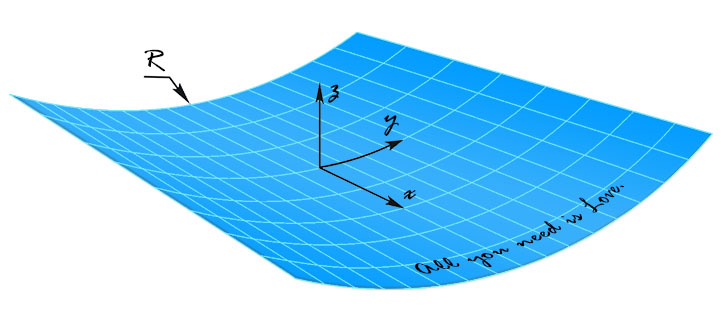
Fundamental Shell Equations Consider a cylindrical composite shell with a radius of $R$, the constitutive behavior of the laminate is described by the ABD-matrix from the classical lamination theory (CLT). Inverting the extensional matrix $[A]$ yields the compliance matrix $[S]$. For the parameters $J$ and $H$, there hold $J=S_{12}+S_{66}/2$ and $H=D_{12}+2D_{66}$. In the current coordinate system $x$-$y$-$z$, the governing equations for membrane and bending deformations can be expressed as: $$S_{22}\frac{\partial^4\phi}{\partial x^4}+ 2J\frac{\partial^4\phi}{\partial x^2\partial y^2}+ S_{11}\frac{\partial^4\phi}{\partial y^4}= \left(\frac{\partial^2w}{\partial x\partial y}\right)^2 -\frac{\partial^2w}{\partial x^2}\frac{\partial^2w}{\partial y^2} - \frac{1}{R}\frac{\partial^2w}{\partial x^2}$$ $$D_{11}\frac{\partial^4w}{\partial x^4}+ 2H\frac{\partial^4w}{\partial x^2\partial y^2}+ D_{22}\frac{\partial^4w}{\partial y^4}+\frac{1}{R^2}\left( H\frac{\partial^2w}{\partial x^2}+ D_{22}\frac{\partial^2w}{\partial y^2} \right) = q + \frac{1}{R}\frac{\partial^2\phi}{\partial x^2}$$ where $\phi$ is the Airy stress function, $w$ is the transverse displacement and $q$ is the distributed load. It is fantastic to observe that this set of equations contains several classical differential equations as its integral parts, viz. biharmonic equation, Laplace equation, Monge–Ampère equation, etc. |
 |
|
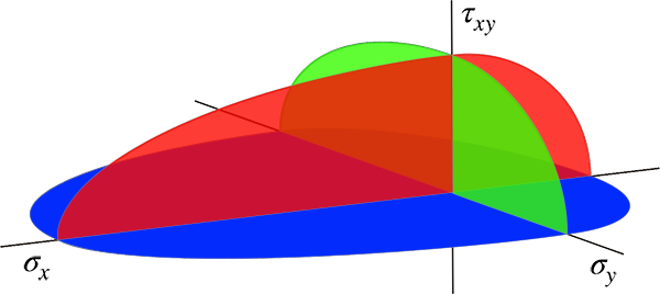
Failure Surface of Unidirectional Composite Consider a unidirectional fiber reinforced polymer composite, its tensile and compressive strengths in the longitudinal and transverse directions are $X_T$, $X_C$, $Y_T$ and $Y_C$, respectively; its in-plane shear strength is $S$. When the composite is subjected to combined in-plane stresses $\sigma_1$, $\sigma_1$ and $\tau_{12}$, it can be deduced from the energy balance principle of Griffith that its failure surface is given by: $$\frac{\sigma_1^2}{X^2} - 2\nu_{12}\frac{\sigma_1\sigma_2}{X^2} +\frac{\sigma_2^2}{Y^2} +\frac{\tau_{12}^2}{S^2} = 1$$ With the help of Heaviside step function $H$, the parameters $X$ and $Y$ are defined as follows: $X = H(\sigma_1)X_T + [1-H(\sigma_1)]X_C$, $Y = H(\sigma_2)Y_T + [1-H(\sigma_2)]Y_C$. It can be seen that this failure surface is a generalization of Beltrami yield criterion dating back to1885, which used the maximum strain energy in its totality, without separating deviatoric and hydrostatic stresses from each other. |
 |
|
Stress Concentration Factor Consider an infinitely large orthotropic laminate with a circular hole loaded under uniaxial tension, it turns out that the governing biharmonic equation can be reduced to an isotropic form by scaling the coordinate axes properly. As a result, the circular hole became an ellipse, and we can make use of the solution of Inglis to determine the stress field in the vicinity of the hole. In doing so, the stress concentration factor is found to be: $$K_T = 1+2\sqrt{\frac{S_{11}+J}{S_{22}+J}}$$ where $S_{11}$, $S_{12}$ and $J$ are the compliance parameters of the laminate as defined before. It should be mentioned that the formula is a reasonable approximation for the general case $J^2 \ne S_{11}S_{22}$. This formula is exact, if there holds $J^2=S_{11}S_{22}$. For a quasi-isotropic laminate, the stress concentration factor becomes equal to 3, which agrees with the solution of Kirsch. |
 |
|
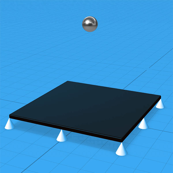
Delamination Threshold Load Consider a symmetric laminate that is subjected to low velocity impact, it can be derived on the basis of damage and fracture mechanics that the upper and lower bound of delamination threshold load can be calculated through: $$P_{cr}^{~u}=\sqrt{32\pi^2G_{IIC}\xi_{min}}$$ $$P_{cr}^{~l}=\sqrt{\frac{32\pi^2(1+\nu_{xy})G_{IIC}\xi_{min}}{3+\nu_{xy}}}$$ where $G_{IIC}$ is the critical mode II energy release rate of the material, $\nu_{xy}$ is Poisson’ ratio of the laminate, and $\xi_{min}$ stands for the minimization of bending stiffness related parameter $\xi$ so that the location, orientation and ellipticity ratio of the first delamination can be determined: $$\xi = \left(\frac{1}{\overline{D}_1+\overline{D}_2}-\frac{1}{\overline{D}_0}\right)^{-1}$$ It has been found that the theoretical predictions are in good agreement with the experimental data. |
 |
|
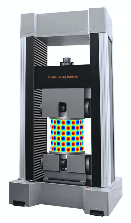
Buckling of Thin-walled Cylindrical Shell Consider a quasi-isotropic cylindrical shell uniformly compressed in the axial direction, the equivalent elastic modulus of the laminate is $E$, the Poisson’ ratio is $\nu$, the laminate thickness is $h$, and the shell radius is $R$. The linear buckling analysis of Lorenz gives a critical buckling stress of the symmetric mode, which is much higher than the empiric formula in Timoshenko and Gere: $$\sigma_{cr}=\frac{Eh}{\sqrt{3(1-\nu^2)}R} \approx 0.612\frac{Eh}{R}$$ $$\sigma_{cr}=E\frac{0.6\frac{h}{R}-10^{-7}\frac{R}{h}}{1+0.004\frac{E}{\sigma_{\scriptscriptstyle{YP}}}} \approx 0.291\frac{Eh}{R}$$ Taking the large deformation effect into account, the non-linear buckling analysis leads to a critical buckling stress of the snap-through mode, which is consistent with the empiric formula: $$\sigma_{cr}=\frac{Eh}{\sqrt{18(1-\nu)}R} \approx 0.289\frac{Eh}{R}$$ This means that the theoretical buckling stress of the symmetrical mode may never reached without special measures in practice, not because the shells are very sensitive to initial imperfections, but because the symmetrical mode is simply not the lowest buckling mode. |
 |